PLCs & Control
Programming, migrations and safety PLCs across Siemens and Schneider platforms. Based in Cumbria, delivering SCADA and automation projects across the North West and UK-wide.
How PLCs work
Plain-English explainer before we dive into the tech detail.
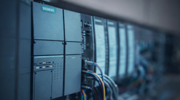
What is a PLC?
A PLC (programmable logic controller) is a rugged industrial computer built to run machinery. It constantly reads sensors and switches, runs your control logic, and then drives outputs to start, stop, or adjust equipment. Unlike office PCs, PLCs are designed for heat, vibration, electrical noise, and long service life. They keep production predictable and safe.
What does a PLC actually do?
A PLC runs in a simple cycle: it reads inputs, executes the program (ladder logic/function blocks), then updates outputs — hundreds of times per second. Inputs can be digital (on/off signals like a limit switch) or analogue (variable signals like temperature or pressure). Expansion modules add the exact mix of digital and analogue channels, plus comms ports, so the PLC matches the plant’s needs.
Because the scan cycle is deterministic, the PLC reacts at consistent intervals, which is vital for safe, predictable control. It’s also built for industrial life: wide temperature ranges, electrical noise, vibration, and long-term availability. That’s why PLCs are preferred over normal PCs for running machinery.
Example: to start a pump, the PLC reads a start button and safety interlocks, runs your logic (is the tank low? is it safe to run?), then energises the pump output. It keeps watching levels and pressures, raising alarms or stopping if something drifts out of range. SES Engineering handles the detailed design and programming — this background is simply to show how a PLC keeps plant equipment running smoothly and safely.
How it thinks
Every scan, the PLC reads inputs (buttons, temperature, level), runs your logic, then updates outputs. It does this hundreds of times a second so control stays predictable and safe.
Inputs can be simple on/off signals or measured values; outputs can be relays, motor starters or speed/valve commands. The cycle is fast and repeatable, even in noisy industrial environments.
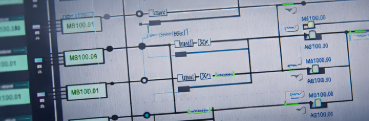
How the scan cycle works
A PLC scan is simple: read inputs → execute the program → update outputs. Inputs can be digital (on/off) or analogue (variable). The logic (ladder or function blocks) then decides what should happen next, and the PLC energises outputs to match. This repeats continuously, giving deterministic timing so actions happen when expected.
Inputs and outputs expand via modular cards, so you get exactly the mix of signals the plant needs. Digital cards capture switches and status contacts; analogue cards handle flow, pressure, temperature or speed signals. Comms ports connect to drives, HMIs and other PLCs for coordinated control.
PLCs are built for industrial life: they keep scanning reliably in heat, vibration and electrical noise. Because the timing is consistent, interlocks, trips and sequences behave the same way every scan. SES Engineering handles the detailed logic and programming so operators and technicians see a clear, stable system they can trust.
Example: on a conveyor, the PLC reads start/stop buttons and safety gates, checks motor status, then runs the sequence to start rollers in order. It keeps monitoring sensors and alarms, stopping or alerting if anything drifts out of tolerance. The scan cycle underpins this predictable behaviour.
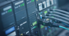
Networking & communication
PLCs talk to sensors, drives, HMIs and other PLCs over industrial protocols. The right mix keeps scans fast, diagnostics clear and cyber risk low.
Networks are built for uptime: managed switches, VLANs for OT, and clean separation from office IT so the process stays protected.
How PLC networking fits together
PLCs use protocols like Modbus TCP, Profinet, EtherNet/IP and Profibus to exchange data with drives, instruments and HMIs. Managed switches and VLANs keep control traffic separate from IT, while firewalls and access rules limit who can talk to what. This segregation is key to keeping latency low and reducing cyber exposure.
Topology matters: ring or redundant links can maintain comms if a cable fails; properly sized networks prevent slowdowns that could affect scan times. Diagnostics from smart devices (status bits, fault codes) help technicians troubleshoot quickly.
Example: a PLC shares speed setpoints with a VSD over Profinet, reads motor status, and publishes key tags to SCADA over OPC/Modbus for operator visibility. External access is controlled and logged so vendors only reach what they need, when they need it. SES Engineering designs these networks so the control layer stays fast, visible and secure.
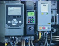
Variable Speed Drives (VSDs)
A VSD controls motor speed and torque so equipment runs smoothly instead of just on/off. SES programs and tunes drives, sets up tension and speed loops, and integrates encoders or absolute encoders so your motors do exactly what the process needs.
The result is steadier conveyors, winders and mixers with less wear and fewer surprises — explained in plain English so non-experts stay confident.
How VSDs work and how we tune them
A VSD takes incoming power, converts it, and feeds the motor with a controlled waveform. It ramps up gently, controls torque and speed, and uses feedback to hold the target setpoint. In closed loop, encoders (incremental or absolute) provide position or speed feedback so the drive can correct drift and maintain tension or speed precisely.
We set up speed loops, torque limits and ramps so motors accelerate smoothly, avoid mechanical stress and stop cleanly. For tension applications (e.g. winding), we tune the loop with encoder feedback to keep web tension stable; for conveyors, we hold consistent speed under changing load. We’re experienced with drives from Eurotherm and familiar with Control Techniques, tailoring parameters to suit each platform without overselling.
Integration matters: drive control words and status bits are mapped cleanly to the PLC, with alarms and interlocks aligned to your safety strategy. Closed-loop tuning is done methodically — adjusting gains, filters and limits until the motor behaves predictably, not nervously. Documentation records the key parameters so future maintenance is straightforward.
SES Engineering focuses on stable, reliable tuning and seamless PLC integration, so operators get smooth motion and engineers have clear diagnostics. We handle the detail; you get drives that start, stop and run exactly as the process expects.
Control types - quick view
- PID control: adjusts outputs smoothly using feedback to hold a setpoint — ideal for temperature, flow, level and pressure.
- PWM control: rapidly switches an output on/off to control average power — useful for heaters, fans or LEDs where fine analogue cards are not required.
- Choosing the right tool: PID gives stable, precise control of continuous processes; PWM is simple, robust and cost-effective when full analogue finesse is not needed.
We tune loops, document settings and test failure modes so the control stays calm, not jumpy, when the real world gets noisy.
Where each control type fits
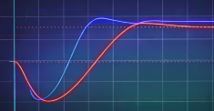
PID control uses proportional, integral and derivative terms to smoothly adjust outputs and hold a target. It’s suited to continuous processes like temperature, flow, level and pressure where small changes matter. Tuning (gains, filtering, limits) keeps responses stable and prevents overshoot or hunting.
PWM control rapidly switches outputs to achieve an average power level. It’s simple and robust for duties like heaters, fans or lighting where fine analogue cards aren’t needed. Cycle times and duty limits are set so equipment runs within safe bounds.
We choose the right approach per loop: PID for tight, stable control; PWM for cost-effective, repeatable power control. Safety and interlocks wrap around both, ensuring pumps, valves or drives only run when permissives are met.
Example: a temperature loop uses PID to hold a setpoint on a heat exchanger, with alarms if it drifts. A small purge fan uses PWM to maintain airflow without the cost of analogue hardware. SES Engineering handles the tuning, documentation and testing so operators see smooth, predictable behaviour.
Services we provide
- PLC programming and code assurance across Siemens TIA/Step7 and Schneider, delivering clean, well-structured control logic built for long-term support.
- Legacy system migrations and panel upgrades planned to minimise downtime, preserve existing operations and modernise ageing control platforms with clear documentation.
- Commissioning support to bring new or upgraded systems online safely, verify correct operation and resolve issues quickly during start-up.
- Troubleshooting and optimisation of existing control systems to improve reliability, performance and operator usability through targeted adjustments.
- HMI and SCADA upgrades including screen redesign, alarm rationalisation and data-logging improvements for clearer, more effective operator interfaces.
- Control philosophy and functional specification development to document system behaviour, guide future upgrades and provide a solid engineering reference for projects and maintenance teams.
- Variable Speed Drives (VSDs) — programming and parameter setup, experience with Eurotherm and Control Techniques, and tuning of speed loops, torque control and tension control using encoder or absolute feedback.
Get in touch
Speak with us about PLC and control projects, migrations or safety upgrades across Siemens, Rockwell, Schneider and more.
Contact us